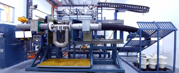
Introduction: why calibration?
Flow meters or flowmeters need to be checked regularly to ensure the accuracy and reproducibility of the instrument. The current regulations set by FDA and GAMP for the pharmaceutical industry and partly already for food and chemical industries require calibration of instruments. Failure to calibrate instruments can lead to a non-validatable process ; which, according to FDA standards, means that no documented proof can be provided that a process can meet – predetermined specifications. As a result, a production process for drugs, for example, can be rejected!
Implementation of calibration and standards:
Calibration allows initial desired settings to be configured and drift phenomena to be verified and adjusted over time. Calibration is initially performed by the manufacturer on its own fixed calibration unit, during operation flowmeters can also be checked using a mobile calibration unit. Very accurate measurements, such as for (energy) tariff measurement and for the calibration of reference flow meters, can be carried out by specialised calibration laboratories such as Delft Hydraulics and NMi. Besides obviously having an ISO9000 certificate, ISO17025 is an important quality standard for companies with calibration facilities . Most flowmeter manufacturers and specialised calibration laboratories are accredited according to this standard.
The following is established and described in ISO 17025:
Management requirements for:
– Organisation
– Management system
– Documentation management
– Contract review
– Outsourcing
– Procurement
– Customer services
– Complaints
– Management of non-conformities
– Improvement
– Corrective measures
– Preventive measures
– Management of quality records
– Internal audits
– Assessment by management
Technical requirements are there for :
– Staff
– Accommodation
– Test methods and validation
– Equipment
– Traceability of the measurements
– Sampling
– Samples
– Quality control
– Reports / calibration certificates
The Council for Accreditation RvA – which until mid-2004 used the name NKO – and the NEN are authorised to issue this standard in the Netherlands.
Fixed calibration units: implementation and use:
The flowmeter is specified by the engineer in a datasheet, which specifies all process data including required accuracies. The following types of flow meters can be selected: magflow meters, vortex meters, mass flow meters, thermal flow meters, turbine meters, ultrasonic meters and dP meters such as orifice flow meters and venturis. The engineer ‘may’ indicate a preference for a particular type of flowmeter, the selection should actually be done by the manufacturer so that they remain responsible for the application of the correct flowmeter.
The required equipment of a fixed calibration unit looks like the following:
A measuring tank for water, usually built into a tower. A variable-pass measuring section into which the flowmeter to be tested is built, taking care to ensure sufficient front and back length of the flowmeter according to ISO/ANSI 5167-2:2003. A collection tray or piston prover (this is a measuring piston, see description below) at the end of the measuring line. A control valve to maintain a constant flow.
Supply pumps that fill the measuring tank with water. Accurate dP transmitters , which are required for dP flowmeters; here the flow = c. √dP in [m³/s].
The water flow can be determined by:
Weight difference measurement per unit time of the tank (according to ISO4185) or of the collection tank ; this is called gravimetric calibration.
Determining the level difference of the measuring tank or collection tank per unit of time .
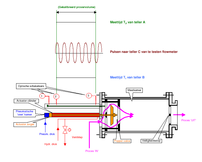
Pushing out a so-called piston prover (measuring piston) with known diameter (D) and measurable distance travelled (ΔL) per unit of time (T) ; thus the measured flow = ( ¼ π.D² .ΔL).1/T in [m³/s]. The piston prover is called ODS Compact prover at the company, see Figure 1. Its operation is as follows: before the measuring stroke, the poppet valve is closed. The liquid then flows into the measuring chamber piston at a constant speed via ‘Process IN’. On this, the measuring chamber piston will move to the right, the measuring stroke is between switches 2 and 3 ; this is the calibrated prover volume.The measuring computer will accurately measure the time between these switches, making the volume flow between them known. After the measurement stroke, the poppet valve is opened to allow the liquid to flow out via ‘Process off’.
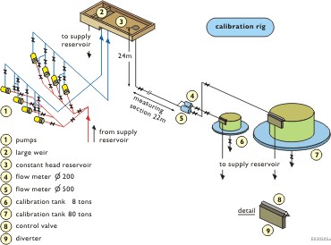
Figure 2 shows the Delft Hydraulics calibration unit, which is constructed as follows:
Pumps (1) and a large spillway length ensure a constant water head from the water reservoir (3)
The measuring section houses the flow meter to be tested. The flow meters (4 and 5) give a real-time indication of the flow. Control valve (8) ensures constant flow in the system. Load cells are built into the calibration tanks (6 and 7) to provide exact weight difference measurement. Also built into this unit are temperature, pressure and density transmitters that allow correction measurements to be made.
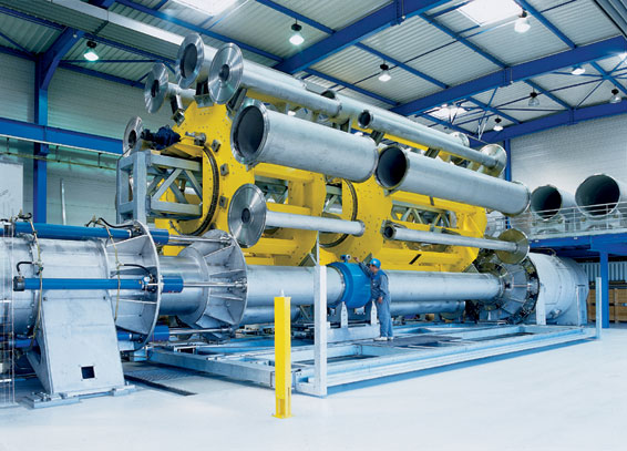
Figure 3 shows the calibration unit as built at Endress+Hauser Flowtec in Cernay France , the measuring tank for water in this installation is built into a 28-metre tower that ensures a very constant pre-pressure in the calibration unit. This allows a very stable water flow to be achieved for accurate calibration.This installation has the Swiss SCS certificate and is accredited according to ISO 17025. In this installation, flow meters up to DN2000 can be calibrated with a maximum flow of approx. 5900 m³/hr . Figure 3 clearly shows the free front and neck length of the flow meter. The large rotating carousel with different pipes can be used to select the correct pipe diameter.
Calibration during operation
FDA and GAMP also require a regular calibration check of flowmeters during operation. The flowmeters can be removed from the pipe for recalibration and sent to a specialised company with a fixed calibration unit or to the manufacturer, this is obviously a costly method. But the flowmeters can also be recalibrated in-situ -i.e. without disassembling the flowmeter- with a mobile calibration unit , this is also an accepted calibration method and is preferable, as evidence of the instrument’s functioning in the installation can then be provided immediately. A reference flowmeter calibrated -at an accredited lab- is built into this unit. There are also mobile calibration units that use a pistion prover flow measurement or gravimetric calibration ; these units are also calibrated at an accredited lab.Several manufacturers rent such mobile calibration units built on a skid or truck. Calibrating flowmeters with a fixed calibration unit obviously remains more accurate. In-situ calibration does, of course, require the flowmeters in the process to be fitted with additional measurement stubs on the inlet and outlet side of the flowmeter to which the mobile calibration unit can be connected. Ultrasonic measurements measuring from the outside of pipe are of course also possible, this flow measurement gives a good indication and verification of the flow but will obviously never be able to achieve the measurement uncertainty of the above-mentioned mobile calibration units ; these meters can therefore not be used for a calibration check as required by FDA and GAMP.
Calibration software: objective and requirements
Managing calibration activities and calibration data is also strictly defined according to ISO9000, FDA and GAMP. This requires the use of validatable calibration software. As a minimum, the software will have to be able to perform the following:
Manage calibration and maintenance activities . Automatically track calibration data and indicate when a calibration should be performed and provide a historical record of this.
Generate calibration reports including measured measurement uncertainties , traceable standards should be used for this.
Printing labels for tested and/or recalibrated instruments.
Providing a high degree of security and access restriction in the form of passwords and using electronic signatures according to FDA21CFR Part 11 so that a validatable process can be met.
The software must have copy protections and backup must be possible.
Many contemporary calibration software packages also comply with ISO17025 , these can, among other things, generate the required certificates and reports so that the required quality registration is met.
The data measured in the field can be entered directly into a laptop on site; software is also available for PDAs from some suppliers.
Measurement uncertainty and traceability of calibration (units)
Calibrations should be traceable, which means that all measurements and tests from the simplest calibration unit to the highest accredited body have been performed and recorded unambiguously. In flow measurement, the term measurement uncertainty is used instead of accuracy. The measurement uncertainty covers the total number of factors of which the measurement deviation consists, such as electronics deviations, temperature and pressure variations. The measurement uncertainty is thus not an absolute concept like the measurement accuracy but indicates with a certain certain certainty within which range the measured value will lie. The attainable measurement uncertainties are: for the specialised calibration laboratories approx. 0.05% and for the simpler fixed calibration units approx. 0.2%. At the end of the calibration, a report will indicate what the measurement uncertainty is and how long it is valid. If working according to ISO17025, the measurement uncertainty is described in standard EA-402 , however, there are still many companies using fixed and mobile calibration units that do not calibrate according to this standard , they maintain their own untraceable (questionable) measurement uncertainty.
Conclusions:
If working according to FDA/GAMP then flowmeters should be calibrated before installation and tested according to a set schedule and recalibrated if necessary.
If ISO17025 is used, strict technical and management provisions apply.
Calibration during operation can be performed in-situ; this is an accepted traceable measurement method and is preferable to dismantling flow meters.
The use of calibration software is required for FDA/GAMP production processes ; software complying with ISO17025 is also available.
If a calibration unit does not comply with ISO17025, the measured measurement uncertainty may be questionable and untraceable.
Explanation of abbreviations used:
ISO : International Organisation for Standardisation , www.iso.org
ANSI : American National Standards Institute www.ansi.org
RvA : Council for Accreditation, www.rva.nl
NEN : Netherlands Standardisation Institute , www.nen.nl
NMi : Netherlands Metrology Institute , www.nmi.nl
GAMP : Good Automated Manufacturing Practices www.ispe.org/gamp/
FDA : Food and Drugs Administration www.fda.org
SCS : Swiss Calibration Service www.sas.ch
EA : European Co-operation for Accreditation www.european-accreditation.org
PDA : Personal Digital Assistant
References:
Flowmeter calibration , procedure and error analysis : Delft Hydraulics
Calibration handbook : Endress+Hauser
Calibration of calibration rigs : Krohne , MPM report 20/05
Operation of compact prover: ODS Jan.2004.
Mobile calibration rig for volumetric testing : Keplan, Justervesenet Norway, April 2001
Guidelines on general principles of process validation : FDA May 1987
EA-4/02 : Expression of the uncertainty of measurement in calibration ; dec.1999

